

There are many methods of modeling..this is a good general purpose method and you only need a handful of commands. In this section we will rough out the model in polygons...no detail, just the overall shape of the object.
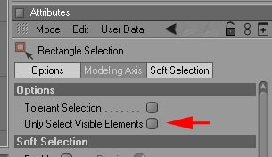
Before we start, I find it easier to not only have the a Q shortcut for Rectangular Selection tool and W for Live selection tool, but to keep the Rectangular tool with the Only Select Visible Elements box unchecked and checked for Live selection tool.
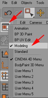
First, select the Modeling layout:
Next, start with a cube, make it editable and switch to the Point tool.
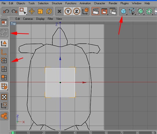
Select the one half of the cube points and move these points to the central symmetry plane (in this case, the YZ plane).

Try to only move the cube points, not the entire cube...you want to keep the origin of the cube on your symmetry plane.
Now in the top/side/front views move the cube points to fit your image plane.
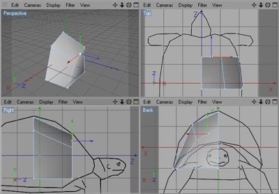
Choose the Polygon tool and select the forward polygon face. Hit the Extrude icon and click and drag Offset in the attribute window to move the excluded face backwards or forwards. You can either scale and move the face in polygon mode or switch to point mode to get individual points to match the image planes.
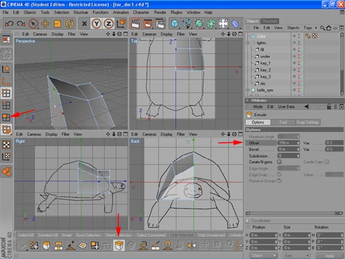
Extrude the back face twice and adjust to the image plane...

Select the bottom four faces and extrude and down. Adjust to the image planes
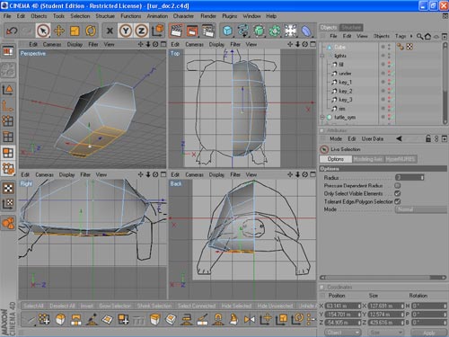
Now is as good a time as any to delete the inside faces of the model. Go to the perspective view select the following faces and hit delete. Afterwards, go to Point tool and look for orphan points and delete those as well...
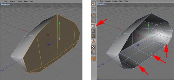
In the front view, use the Knife tool to add an edge between the head and front leg.
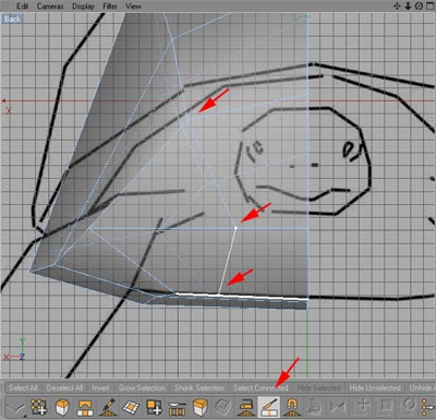
Use the Knife tool again to add edges along the length of the shell from the triangular front face we just created to the back of the shell. Adjust the points to match the image planes.

We now have two quad faces covering the area where the leg and the head attach to the body. Use the Extrude Inner to create a face which will be used to extrude the head. Adjust the points.
Next delete the inner face and drag the inside points of the head extrude face to the symmetry plane...

Now extrude the head and adjust points to the image planes and delete inside faces on the symmetry plane...
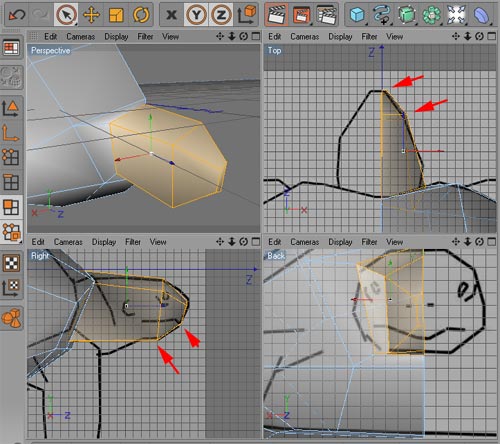
Now repeat this process for the leg. But first, adjust the following three points down and back to give us a better match with the side view image plane.

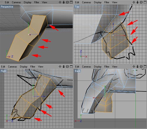
Now repeat the process we used to extrude the head. Select the polygon face that covers the area where the leg attaches to the body. Extrude inner, adjust, and then repeat regular extrudes three times and adjust to the image plane. One of the edge rings must match the knee joint of the leg.

And repeat again for the rear leg...
In the next section we'll switch to Hypernurb modeling and add detail.