

Hypernurbs give you the advantages of polygon modeling (simple predictable interface and UV mapping) with the smooth surfaces you get with Nurbs.
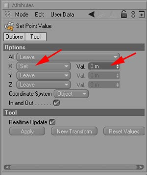
Before we start, make sure we have no inner faces along the symmetry plane. Next we need to set all boundary points exactly on the symmetry plane. In this case, the YZ plane...meaning these points must have an X value of 0. (Likewise, if XY was our symmetry plane, we'd need to set the Z value to 0). An efficient way to do this is to rectangular select the boundary points in the top view (being careful to avoid points close to the boundary, like the turtles nose) and use the Structure->Set Point Value command. Change X to Set and it's value to 0. Y and Z should default to Leave, if not change it to leave. Then hit Apply.
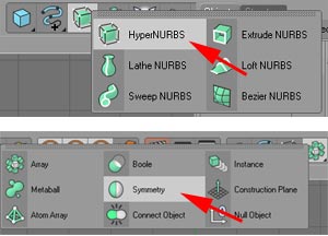
Rename your rough polygon shape as turtle_lores, and create a HyperNURB node and rename it to turtle_hires. Then (if you are working on a symmetrical model) create a Symmetry node:
LMB click-drag turtle_lores on to Symmetry until you see a hierarchy level indicator pointing down. This lets you know that turtle_lores will be a child node of the Symmetry node. Repeat this by LMB click drag Symmetry on to turtle_hires. Your Object Manager should now look like this:
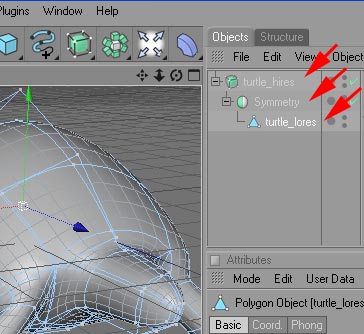
In the view window you should see a smooth symmetrical version of the rough polygon model.
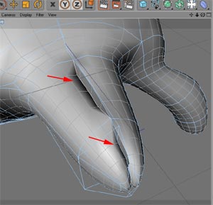
You should not be able to see a seem between to two halves of the smoothed model. If you see a tear or overlap, look for boundary points that are not falling exactly on the symmetry plane and fix them...
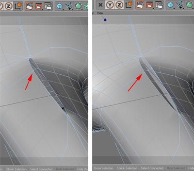
Another problem occurs if you forgot to delete inner polygon faces. That result would look something like this:
Once the hypernurb model looks error free, we will start to add some detail. We'll add some definition to the front opening of the shell and create a lip for both the upper and lower section. I'll start on the bottom to rearrange some of the points and then use the knife tool to add edges.

Until now we've been using the Knife tool in default line mode. Go to the attribute Manager and change to Loop mode

In this mode the cut tool will extend across adjacent faces, allowing a sequence of contiguous cuts with one click. We'll use this to add two edge loops just behind the front edge of the shell. These edge loops will form the front shell lip.

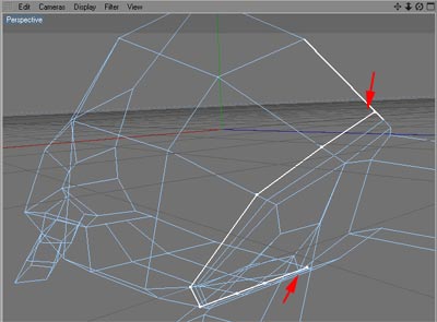
Next we take the thin ring of polygon faces between the two loops we've added and pull them out. You can use any combination of face/edge/point mode and move/rotate/scale to do this. It's important to keep switching back and forth between polygon and hypernurbs, constantly rotating the view to see how this is progressing.


Now to make the lip for the back of the shell. Instead of creating two edge loops to pull out, as we did with the front of the shell, we can select the area inside the back lip and do two short extrudes into the body.
First, complete the edges we added for the front shell lip to the back of the shell. Use the knife tool in line mode and add the following edges...

Select the following faces, and do two extrudes into the body of the model.

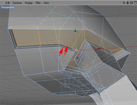
While switching in and out of hypernurb mode, adjust points to to give the shell a more organic look.


Next section will cover the head